Archive
CNC Milling Circuit Boards
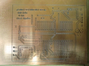
I finally was able to mill a circuit board using my CNC machine. No more acid etching, but I never had much luck with it anyways. After milling the table and fixture, I was held up by the lack of 1/8″ collet, which Bosch doesn’t make. I bought a nice collet set from Think & Tinker/PreciseBits for a modest price and it seems it was worth it. I also needed to buy a license for Mach3 to go beyond the 500 line code limit, since the code to etch the board was near 20,000 lines. To produce the G-code from an EagleCAD project, a nice script is available for free, http://www.pcbgcode.org/. It installs like any other ULP script for EagleCAD and comes with docs to get you going, plus forums and plenty of other websites with tutorials.
It was neat watching the CNC machine cut the traces and no broken bits or other catastrophes. Unfortunately, I didn’t take the time to properly zero the end of the 45 degree v-bit and cut too deep. This washed out the traces and pads, so it’s scrap. Before I realized this though, I tried fiddling with the settings for the pcb-gcode script and kept milling on the sheet of copper clad board and got a lot more bad traces.
The correct way to zero the end of the tool was to use a piece of paper between the board and the tool and to jog down at a very low speed (about 3% of max). While the tool is going down, move the paper back and forth till the tip catches it. Now zero the Z-axis in the Offsets tab of Mach3 in one of special G-code offset codes of your choice. Then measure the thickness of the paper with calipers (my piece was .0035″) and subtract it from the Z offset (press the “Save Work Offset” button to bring up a dialog box that allows you to edit the coordinates). This puts the Z-axis 0 coordinate on top of the circuit board without any pressure. The X & Y coordinates are set to where you want to start milling the board, and can be done by eyeballing it, just don’t re-zero the Z-axis. Now the machine is set to mill.
My settings for pcb-gcode script (not all are included, just what I changed):
Generation Options
Isolation
Default = .0001″
Maximum = .0001″
Step Size = .005″
Etching Tool Size = .007″
Machine
Z Axis
Z High = .5″
Z Up = .1″
Z Down = .002″ (someone posted an excel file in the pcb-gcode forums to calc this, I set mine .001″ higher and it worked)
Drill Depth = .065″ (go a little deeper than the board thickness)
Tool Change
X = 0
Y = 0
Z = .5″ (don’t leave as 0 or the machine will drag the end of the drill bit across the board between tool changes)
Feed Rates
XY = 10″/min
Z = 5″/min
Change any other options you need, then hit “Accept and make my board”. All the files generated will be placed in the project folder with the board. Check out the readme file in the docs folder for explanations, it was helpful. I’ll probably try setting the Maximum Isolation setting to something higher, so the slivers between close traces are removed. I’m sure I’ll update with more progress, or at least to show of stuff I made.
Fixture for PCB Routing
I hope my neighbors don’t mind me milling things late at night. The vacuum is the loudest over the router and stepper motors, so they’ll probably just think I like my house really clean. To kick off my CNC adventures, I’m making a fixture to hold PCBs for isolation routing.
It’s nothing fancy, it mainly helped me understand the CAM portion making stuff. I ended up not using the Sketchup model because of added learning involved to use a script or something, but it can be done. Instead I used CAD to draw the square with the rounded out corner reliefs, then used the CAM software CamBam to setup the stock size and generate G-code. My worst problem was trying to make the coordinate systems jive between the CamBam and my machine. In standard drawing coordinates, the +x goes to the right, while my machine’s +x moves left. This was corrected with an option to set a separate machining origin, and also using offsets in the machines software.
I made the pocket for the PCB slightly larger than the width and length of the raw stock and to a depth of .060″ to match the thickness. The corners were over cut to allow the PCB’s square corners to fit. Next I’ll be drawing up some various clamps to go over the edges to press down. By using some double sided tape underneath, the PCB should be a little higher to give the clamps something to press into. I’m also going to add two locator pins so the fixture can be taken off and put back on in the same place. Built into G-code are places to store fixture locations and makes having multiple fixtures even easier. I milled the main pocket and corners separate and both programs aligned perfectly, Yay!
CNC Machine Table Milled
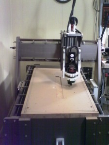
Yay, three times is the charm. My CNC machine finally milled it’s table flat without motors stalling or random nuts coming loose. Since the second attempt, I tweaked the bearing adjustments on the Y-axis and upped the current to all the motors for more torque. The motors got slightly hotter, but not so much that I couldn’t touch them. I also ran the table cutting program a few times without a tool to work out any other kinks.
Cutting the table seemed to take out the inaccuracies from building and you can see in the corners where the high sides were cut shallower than the low side. When I glued the table together I didn’t notice it was twisted slightly on one end. Luckily it could be compensated for in the end.
The run wasn’t without its problems though. Being so pleased with the dust extractor I built, I got a new filter for the shop vac for maximum performance. It was too much for the all-purpose bucket, and the vacuum imploded it slightly and let all the wood dust through to the vacuum. Once the vacuum filter clogged it quit working and the dust went everywhere. Oh well, I bought a new bucket and some extra filtering material and it seems to be working again.
So now I can start making stuff on it, but since I’ve been putting my energy into building it, I’m not sure how to do that. I’ll probably start by making a fixture and hold-down clamps for circuit boards and plastic sheet. I’ve already read some webpages that I’ll try and emulate, so I just need to put it all together.
Second Try & Abort
I took a second shot at planing the table on my DIY CNC machine, but had to abort after several passes. All the new systems were working well, new router, dust extractor and vacuum system, but a rouge nut and washer appeared on the far side of the table. Once the machine was stopped with the E-stop button I found the nuts holding the bottom Z-axis drive shaft bearing mount were vibrating off.
I added some lock washers to all six bolts on the bottom side of the Z-axis carriage to prevent that from happening again. I suppose I should start checking things like nuts coming loose before firing up to cut, so lesson learned. It was lucky the nut and washer fell off out of the way of the router and that I noticed it.
Actually, I needed to restart from the beginning of the program with an offset down to correct a step between the first and second attempts. This also let me check if the new cyclone dust extractor worked on the fine saw dust produced from cutting the MDF board. The shroud made from a CD spindle cover worked rather well for its first real test. I’ll think about adding some brushes around the perimeter later, but was satisfied at how well it controlled the dust cloud that I’ll continue without for now.
Cyclone Dust Extractor
Before I start cutting again, I need a dust extractor to go along with the vacuum. The filter on the shop-vac was clogged with the dust I created from the first run so much it lost suction. Instead of spending $10 every few minutes on filters, I made a cyclonic dust extractor for the same amount. Since anyone with a CNC machine that cuts has one, there are plenty of plans online. I looked at a couple using a 5 gal. bucket and some PVC fittings that looked easy and went with that.
The input to the extractor comes from the CNC machine and to a 90 degree elbow pointed toward the inside wall of the bucket. Then the output to the shop-vac is a single straight piece of PVC pipe, with the end inside the bucket higher than the elbow. Nothing complicated and parts were easily found at the big box store; 2″ PVC pipe section, elbow and two couplings and a general purpose bucket with lid. The hard part was trying to match the two different hose diameters.

Dust filled air enters through the elbow, then falls due to gravity and letting the cleaner air continue to the shop-vac out the short pipe.
After gaining a third section of hose, sacrificed from a junk vacuum in the basement, I was able to make a permanent connection to the shroud and bungee cords. The shop-vac hose hooked to this new hose like it was meant to be, but was a trick to find a compatible PVC piece for the opposite end. I used my dremel tool and ground a step into the inner diameter of a section of 2″ PVC pipe to allow the shop-vac hose to fit into. I’ll still be able to disconnect this section to use the shop-vac for cleaning elsewhere. The last section of hose was an extension kit I bought for a different brand of shop-vacs and was naturally incompatible. One end fits into the vacuum’s input well enough, but the opposite end to the extractor wasn’t near anything. I wound up cutting a slot on one end of a section of 2″ pipe and squeezed the end together with a pipe clamp till the hose fit over. Once the hose was on, the pipe clamp was released and any remaining holes taped over.

The PVC pieces for the output. The two pieces on the bottom are from one coupling cut in half. The smaller half on the right is then cut through perpendicularly to the end.
With the all the fittings made, they need to be connected through the bucket lid. The two holes were cut with a craft knife and care needs to be taken not to rip the material, because it’s easy to do. I scrapped a lid trying to epoxy the two PVC pipes in place, with both times breaking off immediately when moved side to side. Next I sandwiched the lid between two edges of pipe coupling that worked well. For the output section I cut a coupling in half, then cut through perpendicularly on only one of those halves (just one cut so it stays a ring, but opens wider). The solid coupling half goes on the straight pipe section, inside the bucket. On top of the lid, the cut coupling half can expand around the pipe to go all the way down easily. The PVC cement seems to melt the lid material to the pipe and fuses everything securely (and gives off some bonus fumes). The input side also needs a coupling cut in half, but only the piece with the extra cut like before; the edge of the elbow serves as the bottom part of the sandwich.
Once the glue dried and the hoses were connected, I fired up the vacuum to test for leaks. Where hoses met, I sealed with duct tape. Then sealed leaks in the PVC/lid area with some silicone. While the vacuum was on, the wet silicone sucked into holes. I also revised the bungee cord rigging to hold the hose off of the work surface. With the gantry at is furthest position, the bungee cord was wrapped around the hose a few times and held in places with zip ties. When the gantry moved back to home, the hose naturally coils against the wall and out of the way. From the pic below, it looks like the cord is pulling hard on the hook in the wall, but there is still some slack left.
Eventually, I’ll move both the dust extractor and vacuum in the basement, with the switch controlled by the CNC software. But that will have to wait till I actually make something.
New Router for CNC Machine
Yay, Santa came through on the new router for Christmas, albeit a little late (he wasn’t sure what size I needed and was in my area on Santa business). It’s a Bosch 1HP palm router featuring a speed selection and detachable handle for a nice circular area to hold on to. Naturally, it was smaller than CNC router holder and the adapter for the other router.
I tried and failed at a complicated three-jawed system within the old adapter before getting new material. By chance, I found the same diameter PVC pipe, but with a thicker wall and made it work by cutting out an inch section and the pipe was able to close over the router body. A notch had to be cut on the bottom side to allow access to the shaft holding button (or whatever its called).
The tool holder is squeezed pretty tight, so a new one may be the first project. Before that the table still needs to be milled flat, which I guess is the next step.
CNC Update – Router Teardown
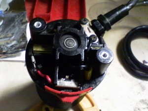
The router shutting off for the split second while the CNC machine was moving started all the problems during the first cut, so that has to dealt with. A search for my Craftsman router model 315.17351 didn’t turn up much more than that it’s been discontinued, so no new parts. All I really need to do anyways is clean the switch and motor contacts; both bearings seemed fine. Taking it apart was easy enough by the two screws holding the cover and then popping out the two brush assemblies to reveal two more screws holding the motor assembly to the outer case. I was then able to clean the motor contacts with some scotch-bright and alcohol, along with the carbon brushes. The switch was cleaned and lubed with a small, expensive spray can of contact cleaner.
Putting it back together was the tricky part. The motor assembly was held inside the outer case with a plate and two pieces of metal, and I couldn’t see how they were positioned when together. A lot of tries and cursing finally solved it, so I took a picture and the peasants rejoiced. Yay.
The two blocks are angled on the ends so the top edges push out and lock inside matching ridges on the cover. For orienting the blocks, the thru hole is oblong on the side touch the motor windings and broad flat side out. The screws are only threaded to the plate to hold it on, and allows the whole assembly to slide inside the case. There is a notch and tab for alignment.

Almost all back together, with no extra pieces! Note which side the wire nut is on, because that's where it doesn't hit the spinning parts.
After tightening the screws, reroute the wire through the notches, press the switch in place and check to make sure the wire nuts aren’t rubbing ton the spinning part (mine was), then put the cover back on. A quick test seemed to show it was working better, I guess.
CNC Update – Dust Collector
I always knew I’d need something to collect the chips and dust the CNC machine was bound to make, but I was thinking that it would be one of the first projects completed after the machine was operational. After the dust settled from the first cut, a case of wooden boogers changed my mind, so now I need a system in place before the next cutting attempt.
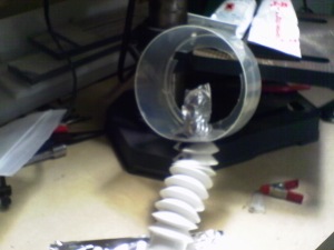
A CD spindle cover was on top of my junk box and a perfect match for the router holder which formed the base for the rest of the project. The next challenge was the difference in height from the bottom of the tool holder to the bottom of the Y-axis carriage and the connection to the shop-vac. Some wandering and staring at products in a big-box home store led to a flexible drain pipe and hose extension kit for a grand total of $25 (I already had the shop-vac). Back home, cutting the CD cover was a pain, but was eventually done and the flexible drain pipe modded slightly as well. At first, the CD cover and drain pipe was fastened with a screw and sealed with silicone, but that ripped apart on the first trial run. Once the silicone was clean off, I liberally applied some JB Weld epoxy, which ended up reinforcing that part of the CD cover as an added bonus. Last, the other two bungee cords from the dollar store three pack were arranged to hold the vacuum hose off the work surface.
I might extend it further down with the shower curtain or some thick plastic bag material and the bottom half of the CD cover. We’ll see how it performs during the next round of cutting and maybe I can get the table surfaced. Right after tearing down the router and giving it a good cleaning.
CNC Update – First Cut & Catastrophe
News everyone. Quite the excitement this morning seeing the CNC machine perform it’s first cut, then flake out and go slightly nuts. Lucky for me the stop button still worked and no harm was done. This happened while attempting to mill the table flat so I can mill real stuff.
Anyways, a couple things happened at once. The router turned off suddenly during a move, causing the motors to skip and the machine jammed slightly. I hit the emergency stop, got the router going and restarted the program, but the machine went off cutting in the wrong direction. Blast, now I’ll have to start over after re-zeroing. Also, my cheap-o pendant started having issues with Windows and was causing mayhem.

The black mark in the middle of the cut area was a missed screw that gave a little firework show on the first few passes.
So that was my first try at milling. I took out the tool from the router and let the entire program run, with no problems. When it was cutting though, it’s clear I’ll need a dust collection device ASAP. Right after I rebuild or rebuy the router…
CNC Update – Router Mount Adaptor
I picked up a router for my CNC machine at a pawn shop that was slightly too small for the holder, of course. After spending a few bike rides trying to come up with a way to fill a gap of about 1/4”, the solution was rather an easy one.
A piece of schedule 30, 3″ pipe had the right outer diameter, but was slightly too small for the router body. Luckily before Hammer Time came, I cut the pipe lengthwise and it slid over nice and snugly. Naturally the plan didn’t go off without its hitches and had to buy the whole 10 feet of pipe to get the 3-1/2 inches needed. At least the two competing big-box stores are neighbors, because one was dramatically cheaper than the other.


